TenderJobs

SINS Gang - Ship's Inertial Navigation System

Navigation Repair Division (W5), Weapons Department

The purpose of the Fleet Ballistic Submarine is to be a mobile launch platform from which retaliatory strikes can be launched against an aggressor against the United States. What makes the value of the FBM Sub so great - is that being mobile and un-detectable - a potential aggressor cannot preemptively strike them and remove the retaliatory threat - in other words - attack the United States - and know that you are going to pay a serious price - because the 41 will answer with all their furry.

In staying "un-detectable" a problem arises that must be overcome for the threat to be credible: accuracy. When you launch a weapon several hundred to a couple thousand miles - and expect it to hit it's target - the missile's navigation must be extremely accurate: a small error at launch can accumulate to dozens of - or even a hundred miles off-course at the end of several hundred miles of flight.

So two things must come together to get the weapon accurately to it's target: 1) the missile's own guidance system must be extremely accurate; and 2) the starting coordinates (latitude and longitude) upon which all of the rest of the flight is based on must be exact - within - not degrees, nor minutes, but within just a few seconds of degrees - latitude and longitude. A degree of Latitude is approximately 60 nautical miles. So a minute is a mile - and a few seconds (60 seconds in a minute; so a second is 101 feet) - well you get the idea! (a nautical mile is 6,076.1 feet).

On an FBM submarine - this positional data - precision latitude and longitude - is supplied by a subsystem called the Ships Inertial Navigation System - SINS for short. SINS has three main component groups:
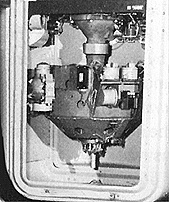
1) the binnacle - which contains the stable platform, gyros and accelerometers.
2) the SINS console which contains the servo electronics to keep the stable platform level, and oriented correctly.
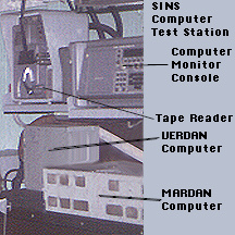
3) the navigation computer - which integrates the various inputs from all of the components and generates orientation data, tracks and follows earth rotation, ship's motions, and integrates acceleration into speed data; speed into distance; and distance and direction into latitudinal and longitudinal coordinates - plus - roll, pitch and heading data which are fed to various other systems throughout the boat (navigation, fire control, missile guidance data, etc.). The computer is actually in the bottom drawer of the console.
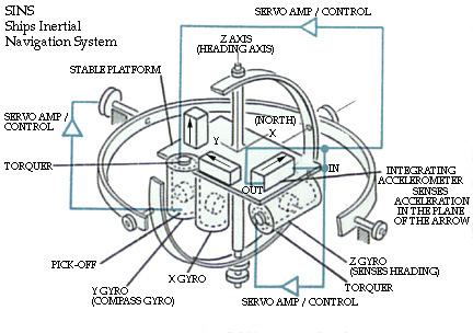
The platforms can be erected, leveled, and calibrated with the boat at sea - however - since this complicates the "basic" operation - for the purpose of this explanation - we're only going to talk about doing this while tied to the tender - i.e. dead still. The stable platform is called "stable" because it is kept level - and referenced to true (not magnetic) north. It can be kept this way by taking advantage of several natural laws of physics.

There are three accelerometers - devices that detect and measure acceleration forces - one in each of three perpendicular planes: north-south; east-west; and vertical. Any movement in any plane is sensed by these accelerometers and sent to the computer. Note that the vertical accelerometer will "feel" gravity at all times. If the platform is level - the other two accelerometers won't "feel" any gravity at all --- if the platform "tips" slightly - one or both of the east or north accelerometers will start to "feel" gravity. This is how the platform is leveled to begin with: move the platform to minimize gravity in those two planes.

The gyros are designed to "sense" any attempt to rotate them about their input axis - and since there are three of them - each in a perpendicular plane to the others - any roll, pitch or heading rotation is sensed - and the computer generates a torque signal to return the platform to level. Since it is always level - the angle between it and the boat represents roll or pitch. Once a platform is "leveled" using the accelerometers; the gyros keep it level.

This has us level - now we need to get it "pointed" north. Actually the platform can (and does) operate pointed in any direction - the computer automatically "handles" any bearing orientation - but to keep this explanation simple - we're going to keep the "north" gyro (and it's associated accelerometer) pointed "north". As noted - the gyros are designed to detect any attempted movement around their input axis. Since we have two gyros in the horizontal planes (the platform is level now, remember) - the only force either should feel - is the Earth's rotation (maybe we can stop - but this planet isn't going to wait!). If you keep the platform level - and rotate it about the heading axis until the east pointing gyro no longer feels the Earth's rotation - it is pointing exactly east!

Now that we have the platform level and referenced to true north - we're ready to navigate! Any motion by the Submarine is sensed - and 1) fed back to the platform to keep it level and pointed north - and 2) is used to determine roll, pitch and heading. Any acceleration on an axis results in speed, direction - and ultimately latitude, longitude and depth all being calculated and made available to the boat's other systems. If you think you've followed along pretty well so far - great! - now imagine erecting, leveling and calibrating a SINS - at sea!... Yup - SINS techs do it all the time.... It's their job.

Nothing man-made is perfect - no machinery is totally "perfect". So it is with SINS. The gyros drift. There is an "infinitesimal" delay in torquing the platform. There is friction. The accelerometers are far from perfect too! And gravity is not constant (nor always straight down, for that matter - an under water mountain will distort gravity!). These and other factors cause errors. From the earliest days - the computer could compensate for gyro drift - by applying small "torquer" signals to offset the drift (called precess). This number was calculated by the SINS techs - and entered into the computer - and manually adjusted as needed. One of the great additions to the more modern systems was the addition of a fourth gyro - mounted on it own rotating platform - on the side of the stable platform. This "monitor" gyro, of course, has errors of it's own. But since it can be rotated 180 degrees - the error self cancels. And since it can be rotated in 90 degree increments - it can "monitor" either the East or North pointing gyro as needed. This allows the computer to check and calculate precess correction for both of these gyros.

Because of these "accumulating" errors - the SINS needs to be checked - and re-calibrated every so often. The boat can get fixes from Satellite (GPS), Loran C, Sonar, and other sources. All of this "fix" data is fed to the NAVDAC computer (Navigational Data Assimilation Computer) - which compares the results with the SINS - and calculates correction data - which is fed to the SINS computer. These other systems form the other "Navigation Specialties" NavAids Technicians: Loran, Satellite, Sonar (navigation); and Digital Technicians: the NAVDAC equipment.

Autonetics VERDAN MBL-D9A Computer

and

Autonetics MARDAN (also known as Verdan II)

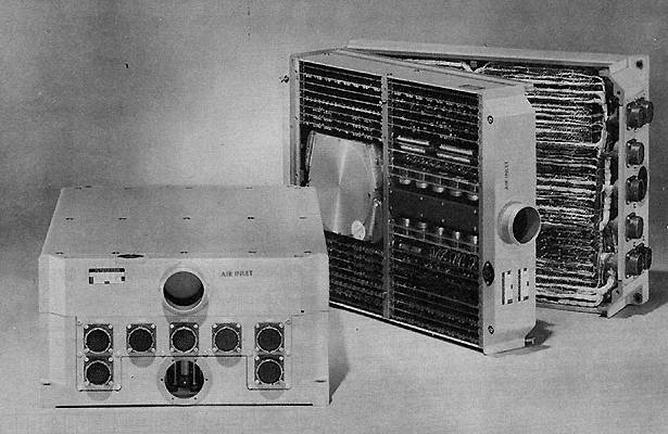
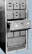
Verdan - complete computer on left - opened for service on the right. Notice the power supply - with it's transformer and huge transistors right by the air intake-- the rotating magnetic memory (which is not only the permanent memory - but the working registers as well!) is to the left of the power supply.
Photos courtesy Autonetics. Data from the Ballistic Research Laboratories Survey of Domestic computers - BRL 1961 and BRL 1964.
Designed in the late 1950s and early 1960s these computers were the brains that made SINS posible. When you consider that from the standpoint of raw computational power - these have only a small fraction of the computational power and speed of today's personal computer - in fact most medium level or higher pocket calculators have more power and speed. Yet- these computers handled some than 54 inputs (90 in the case of Mardan) most of them either analog, or pulse-rate data that had to be converted to digital through either Digital to Analog converters or integrated against time. And those time integrations had to be dead accurate - as any error would quickly ramp the system out of allowable accuaracy. Consider the daunting task of counting three pulse streams against time; converting the inputs from 32 encoders (at 20bits each); and converting 16 analog channels (again 20 bits accuracy each) --- ALL at the same time ---- AND calculating accelleration against time in three
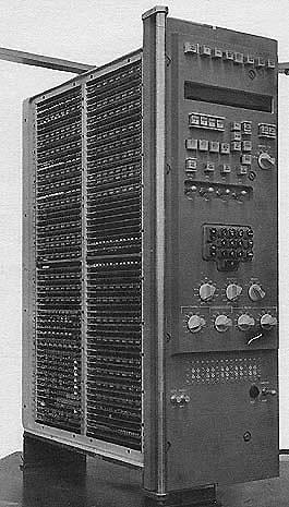
Mardan - The control panel attaches to the front - making a more compact installation - considering it's roughly twice the power of Verdan.
dimesions (equals speed and bearing (vector) speed and bearing again against time is distance traveled - ALL at the SAME TIME! This is what both Verdan and Mardan are capable of. Mardan's extra capabilities were used to perform extra calculations for confidence, calibration, and redundancy. I invite those of you who are computer savy to look over the follow specifications - I think you'll marvel at how much was accomplished with such early technology.

Manufacturer's Specifications and Data

APPLICATIONS
The computer is designed primarily for solving real time control problems by combining, under program control, a general purpose computer and two digital differential analyzer sections. The computer can be used as the central computer in control and weapons systems. It has the capability of simultaneously extrapolating points along many functions, computing new initial conditions, accepting and processing time varying data from 54 (Verdan) / 90 (Mardan) different sources, and controlling 40 (Verdan) / 47 (Mardan) different output devices. The GP and DDA sections operate simultaneously and independently, however the DDA program can be controlled, monitored, and modified by the GP section under GP program control.

Programming and numberical system
  Verdan Mardan (Verdan II)
Internal number system Binary Binary
Binary digits/word 24 27
Binary digits/instruction 22 24
Instructions/word 1 1
Instructions decoded 52  
Arithmetic system Fixed Point Fixed point
Instruction type One and 112
address format
Operand sector & channel
+ next instruction sector
Number range As Integer:-(223 <= W < (2 23 -1)
As Fraction:- 1 <= W < 1 - 2 -23
± 8,388,607 (Fractional)

Instruction word format Verdan
0      1 2            8 9       12 13  16 17   23
Not Used Sector of Next
Instruction
Operation
Code
Channel Sector
Operand Address


Instruction word format Mardan
24    22 21       16 15     11 10          1
operand
address
next
instruction
operation
code
operand
address
channel sector

Registers and B-Boxes (Mardan Only)
1 - 25-bit Intercomm. Buffer Register
2 - Rapid Access Registers, 8-word, 16-word
4 - Arithmetic Registers

ARITHMETIC UNIT
Operation
Verdan
Including
Storage Access
Verdan
Excluding
Storage Access
Mardan
Including
Storage Access
 
Microsec
Microsec
Microsec
Add
160
80
78
Mult  
2,000
2,000
Div  
2,000
2,000
Arithmetic mode   Serial
Timing   Synchronous
Operation   Sequential

Storage
  Medium No. of Words No. of Bin
Digits/Word
Access
Microseconds
Verdan Magnetic Disk
1,664
24
5000 (average)
Mardan Magnetic Disk
5,632
24
156 (optimized)


Input
Verdan
Mardan
Media Number
Speed
Number
Speed Remarks
Discrete (none)  
20
Variable1,000
pulses/sec max.
(Read under GP program control)
Resolver 3 Incremental
(using 9 integrators)
800 times/sec
  Variable 1,000
cycles/sec max.
(DDA program control)
Pulse 3 Ternary
coded pulse
(using 8 integrators)
800 times/sec
  100 pulses/sec (DDA program control)
Analog 16 Inputs
+/- 0.5%
Range +/- 10V
100 times/sec
  Continuous (DDA program control)
Encoder 32 Inputs
20 significant bits
100 times/sec
  Continuous (DDA program control)

Operator inputs are keyboard, typewriter, or punched tape.

OUTPUT  
 
Verdan
Mardan
Medium # Speed Remarks # Speed Remarks
GP channel & timing        345,600 cycles Continuous
Discrete      
8
100 pulses Control external devices
Incremental (Binary) 4 100 times/sec     100 pulses DDA information)
Incremental (Ternary) 4 100 times/sec     100 pulses DDA information)
Analog 15 100 times/sec +/- 0.5% Range +/- 10VDC   Continuous Two format options, 20-bit precision.
Shaft Positioning 16 100 times/sec 20 significant bits   Continuous  
Serial Digital 1 332.8 Bits        


Operator outputs are the Nixie display of any memory location by setting up of location selection switches, the display of continuous output either manual or programmed, typewriter, or punched paper tape.

CIRCUIT ELEMENTS OF ENTIRE SYSTEM (Verdan only)
Type Quantity
Diodes

10,000

Transistors

1,500

Capacitors

670

Resistors

4,500


POWER, SPACE and WEIGHT
  Verdan Mardan
Power 400cycle 3Phase 0.320Kw 0.8pf 0.925Kw.
Volume 1.4 cu. ft. 3.0 cu. ft.
Weight 82 lbs. 180 lbs


PRODUCTION RECORD
 
Verdan
Mardan
Number produced to date
180
61
Number in current operation
180
33
Number in current production  
49
Number on order
883
110
Anticipated production rates
5/week
4/week
Time required for delivery
10 months
7 months


PERSONNEL REQUIREMENTS
This computer was primarily designed for unmanned control systems and thus can operate for long periods of time unattended. Training made available by the manufacturer to the user includes programming course and operation and maintenance course.

COST, PRICE AND RENTAL RATES
Basic system consists of the computer - VERDAN, manual control panel, and paper tape reader. Additional equipment includes paper tape punch, tape prep. equipment, test equipment - C297A, and typewriter. Prices are available upon formal request to Autonetics.


Table of Jobs

© 2006 Common Cents Computers